This is the first of a series of posts to follow. I will describe my attempts to build an ultrasonic wind meter (anemometer) based on an Arduino Uno. By the time of writing, I have a working prototype but it will take me a while to catch up in this blog. So this is just the first post – more will follow soon.
Click here for an overview over this series of posts on the anemometer project: https://soldernerd.wordpress.com/arduino-ultrasonic-anemometer/.

Let me quickly outline the project: My aim is to build an ultrasonic anemometer based on a Arduino Uno board. Now what’s an anemometer? That’s just a fancy name for a wind meter. I want to be able to measure both wind speed and wind direction with high accuracy. Most wind meters are of the cup or vane variety. They turn wind into mechanical motion and then measure that motion to calculate wind speed and possibly direction. An ultrasonic anemometer on the other hand sends and receives ultrasonic pulses and measures the time-of-flight. From the time-of-flight (or the time difference, depending on your approach) you can then calculate the wind speed in a given direction. Add a second pair of senders and receivers at a 90-degree angle and you get both wind speed and direction. As so often, wikipedia gives a nice overview/introduction to the subject: http://en.wikipedia.org/wiki/Anemometer

Surprisingly, there seem to be very few people out there who have done this before. Basically, there is this one brave guy named Carl who has built such an anemometer from scratch and put all the relevant infomation online.His project was published on hackaday.com and this is where I found it: http://hackaday.com/2013/08/21/ultrasonic-anemometer-for-an-absurdly-accurate-weather-station/. All of his documentation can be found here: https://mysudoku.googlecode.com/files/UltrasonicAnemometer.zip. This material makes for an excellent starting point if you want to build your own. I’ve looked carefully at Carl’s schematics and have copied many of his ideas. I did end up changing quite a few things and will explain my reasons for doing so but the general approach is very much the same. Many thanks for sharing this with us, Carl.
The basic idea is simple: You send a ultrasonic pulse and measure the time until it arrives at a receiver located in some distance. Ultrasonic transducers often operate at 40kHz and so do mine. A transducer is a device capable of both sending and receiving a signal. It’s the kind of thing cars uses for their parking aids, telling you if there is an obstacle and at what distance.

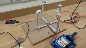
In a 2-dimensional anemometer such as here, you will have 2 pairs of transducers for a total of 4. Let’s call them North, South, East and West for simplicity. You need to be able to send and receive pulses in all 4 directions: N->S, S->N, E->W and W->E. Not all at the same time but one after the other.
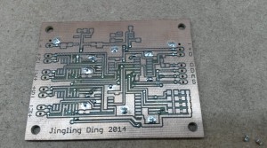
So you will need some kind of circuit to route your signals from and to any of the transducers. For example you want to send from the West transducers and receive from your East transducer or vice versa. Let’s call it the digital part even though the received signal is analog in nature. The PCB without components just above is the basis for this digital part. If you wonder who or what Jingling Ding is: That’s the name of my step daughter who helped me drawing and laying out this PCB in Eagle.
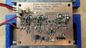
You will then need some more circuitry to process the received signal. This circuit is shared among the 4 transducers so only one can be listening at any point in time. That’s why the digital part needs to route the signal from the correct transducer to this signal processing circuit. The received signal is analog in nature and will be very weak compared to the transmitted one. So you will need quite a bit of amplification first. But this analog signal cannot directly be used by your arduino to measure the time of flight. You need some digital signal(s) that you can measure using the timer(s) on the arduino’s Atmega328 chip (in case of the Arduino Uno). Let’s call this the analog part. That’s what’s shown on the photo at the top of this page.
In my next post I will go through the details of the two circuits. Click here for the second post: https://soldernerd.wordpress.com/2014/11/15/arduino-ultrasonic-anemometer-part-2-digital-circuit/

Lukas,
The version2 from Carl he mentioned, this one is not working either.
The mods you made are these done on the version 2 from Carl?
Because I have version 1 from Carl and I would like to give it unother try to get the system working.
So that means I must make the version 2 PCB,s with your mods. This will work is this correct?
Regards,
Theo
ps. This is my second replay because I wrote the arduino forum and carl47 till latest comment.
LikeLike
Hi Theo
Thanks for your comment. I’ve used Carl’s project report (that 31 pages PDF file named ProjectReport.pdf from the zip file that I have linked above) as my starting point. From all I know this is the (working) version he had originally built and and submitted to hackaday.com.
I have drawn my schematic from scratch and haven’t even looked at Carl’s PCB layout. I basically looked closely at his circuit, liked many of his ideas but then drew my own schematics and layouts.
I have a working prototype sitting here in front of me so the circuit as posted here work with the following limitations:
– As I wrote and can be seen on the photos I’ve messed up some signals on the digital board and had to correct his manually. The schematic and board I’ve uploaded (RevA) are what I have used so they still include those mistakes. I’ll upload a corrected RevB when I get time.
-On the analog board I had to change some component values to get the desired gain. But the design works and the layout is correct.
As I write this, I’m already working on a second version that comes as a standard Arduino Uno sized shield. So there is only one board that you just stack on the Arduino. I have the PCB here but haven’t put any components on it yet so I can’t tell for sure if it will actually work.
So as you see, the project is a bit ahead of my blog posts but I’m trying hard to catch up.
LikeLike
I want more about components,which specific types of transducers,size etc
basically nature of the tranceducer
please suggest
LikeLike
The transducers I’m using are Multicomp MCUSD16A40S12RO, Farnell number 2362677. They cost around USD 5 in small quantities.
LikeLike
i believe it works but in what way? does the wind blow the US waves away? Also. as the speed of sound through air isnt there a temperature compensation necessary?
LikeLike
Yes, speed of sound varied considerably with temperature and this needs to be compensated for. But this is quite easy to do by just measuring the temperature (there is a temperature sensor on the shield) and doing the math with the adjusted speed of sound.
LikeLike
I don’t understand why there is an additional temperature sensor necessary.
If you do two measurements of time-of-flight, one in forward direction and one in backward direction, you get t_plus = r/(c+v) and t_minus = r/(c-v) with distance r, speed of sound c and windspeed v. Now you have two equations for two unknowns.
=> c=r/2(1/t_plus+1/t_minus) and v=r/2(1/t_plus-1/t_minus)
So you don’t have to take c(T) into account and no need to measure temperature T. Instead you get c for free and from the inverse function T(c) you can calculate the virtual temperature T of the air!
LikeLike
Hi Martino. You are correct, if you consider only one axis, you have two equations with two unknowns – perfect. With two axis, things get a bit more involved: You now have 4 equations with 3 unknowns (because the two temperatures have to be identical). So you have an over-defined set of equations for which you need to find the best solution (say, least squares). I’m not particularly familiar with this kind of math but it it probably means doing some Householder transformations on a matrix and the like. And you need to make sure your approach is numerically stable. Probably doable but not straight forward to do in a 8bit microcontroller.
So, to start with it’s probably sensible to measure temperature and have only one equation per axis (using the difference in the time-of-flight). Nevertheless, if you have some ideas or insights how this kink of over-determined system of equations should/could be solved I’m very interested
LikeLike