Tag Archives: analog

Arduino MPPT Solar Charger Shield – Software

There have been two previous posts on this project: one on the concept and the hardware and one on hardware testing. You probably want to check them out first if you’re not yet familiar with this project. Or even better: Click here for an overview over this project.

20160212_Projekte_045
Maintaining an input voltage of 17 volts even if that means a lower-than-desirable voltage at the output

Now that we know that we have a functioning MPPT solar charger we are ready to talk about the software (or the sketch as the Arduino folks call it). It’s quite simple, really. So this will be a short post. And yes, you can download the sketch. There is a link at the end of this post. As always, I appreciate any feedback, comments and the like.

There is a number of basic tasks the arduino needs to perform in order for this shield to be useful. I’ll go through them one by one.

Controlling the DC-DC converter

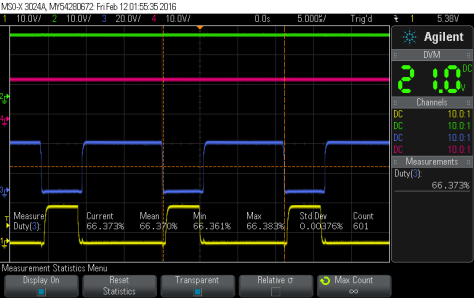
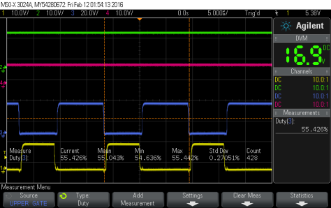
At the heart of this project there is a synchronous step-down (or buck) DC-DC converter that is controlled by a PWM signal from the arduino. So one of the tasks is to set the frequency and duty cycle of that PWM signal.

We let the PWM signal run at the maximum frequency the arduino allows with an 8 bit resulution. Thats simply 16MHz (the Arduino’s frequency) divided by 256 (the 8 bit resolution), or 62.5 kHz. So the prescaler will be 1.

As you can see from the shields’s schematic, we need to output the PWM signal from Pin 6 (by the Arduino’s pin numbering, not Atmel’s). In order to do this kind of low-level stuff you’ll have to read the Atmega328’s data sheet. There is usually no Arduino-ish shortcut if you really need to controll what’s going on.

Luckily it’s just a few lines of code to set things up. All in the function buck_setup(). There are three more little functions to control the DC-DC controller once it’s set up:

buck_enable() and buck_disable() are very simple and just turn it on  and off, respectively. buck_duty(uint8_t duty) is only slightly more involved. It changes the duty cycle to the value you pass to it. Besides that it ensures that the duty cycle stays within certain limits.

20160212_Projekte_042
Test setup with resistor-based dummy load

You don’t want it to go to 100% since in order to keep the bootstrap capacitor C6 charged you need a little bit of off-time. In order to drive the upper FET you need a voltage higher than the panel’s voltage and that’s exactly what C6 is for. So we enforce an upper limit on the duty cycle.

Likewise, you don’t want your duty cycle to go below 50% because in that case you would be pumping energy from the battery to the pannel. A synchronous step-down converter is basically the same thing as a synchronous step-up (aka boost) converter with input and output confused. So we also want to enforce a lower limit on the duty cycle.

The upper and lower limits are set through the #defines DUTY_CYCLE_MINIMUM and DUTY_CYCLE_MAXIMUM.

Measuring voltage and current

The shield has all the hardware necessary to measure both voltage and current both at the input as well as on the output. We’ll just need to write some simple software to make good use of that hardware.

Unlike with the PWM singal where we had to do some low-level bit fiddling ourselfs we can just rely on convenient Arduino library functions to do the job. Basically, analogRead() is all we need here.

20160212_Projekte_043
Nicely regulating so that the input stays at 17 volts

I’ve written a function called read_values() that uses analogRead() to read all 4 values (input voltage, output voltage, input current and output current) 16 times each, averages the results and converts the ADC reading to proper voltages and currents.

The necessary multipliers are defined as floats in VIN_MULTIPLIER, VOUT_MULTIPLIER, IIN_MULTIPLIER and IOUT_MULTIPLIER. I’m doing all the voltage and current measurements in floating math. Yes, this is not at all efficient but we don’t need the Arduino’s computational power for anything else most of the time so this is fine here. Just keep in mind that you can save a lot of resources here if you ever need to do so.

Displaying voltage and current on the LCD

Our hardware also involves a 2 lines x 16 characters LCD so we can show the world what we are measuring. Again, we can rely on standard Arduino functionality to do the job. There is an LCD library that does everything we need.

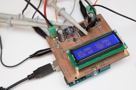
So my function write_display() can focus entirely on formatting. The upper line shows the voltages in Volts, the lower line shows the currents in Milliamps. The input is on the left hand side of the display, the output on the right.

Deciding what to do

In the first section we’ve discussed the functions necessary to controll the DC-DC converter. But in order to use those functions, the Arduino needs to first decide what to do.

Vin21
66% duty cycle at 21V input voltage gives the desired 13.8V at the output

This is where the function buck_update() comes into play. You could consider this the heart of this sketch. This is where all the relevant decisions are made. When to turn the converter on, when to turn it off, when to increase the duty cycle, when to decrease it… You get the idea.

The behaviour of buck_update() is controlled by 8 #defines. I list them here together with the values I have used:

#define ENABLE_VOLTAGE 18.0
#define DISABLE_VOLTAGE 15.0
#define INPUT_TARGET_VOLTAGE 17.0
#define OUTPUT_TARGET_VOLTAGE_LOW 13.8
#define OUTPUT_TARGET_VOLTAGE_HIGH 13.9
#define INPUT_CURRENT_LIMIT 2000.0
#define OUTPUT_CURRENT_LIMIT 3000.0
#define INPUT_CURRENT_MINIMUM 0.0

I think they are quite self-explanatory, especially if you look at how they are used inside buck_update. It’s quite simple: If the panel’s voltage rises above 18V, turn the converter on. Once the converter is on, try to archieve a panel voltage of 17V without exceeding 13.9V at the output. If the panel’s voltage drops below 15V turn the converter off again.

Vin17
At 55% duty cycle with a 16.9V input voltage we’re getting only around 9.2V at the output

Besides that the function is also looking at the input and output current and makes sure certain limits are not exceeded. But with a 30W panel it should never be possible to reach those limits anyway.

Putting it all together

Now all we need to do in the loop() function is calling read_values(), buck_update() and write_display(). Since writing to the LCD is quite slow we are only doing it every 32nd time we read the values and update the PWM signal.

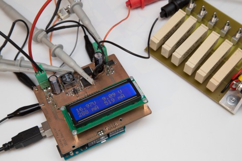
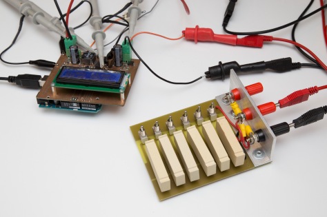
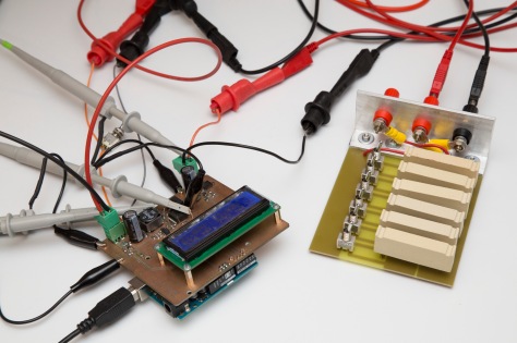
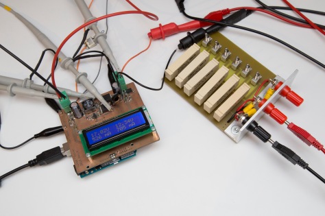
With this sketch I’ve hooked the MPPT Solar Charger up to my lab power supply. (a Keysight E3645A, my newest toy *g*) and my extremely simple but occasionally useful resistor-based dummy load.

The enable and disable voltages are simple and work as expected. Maximum output volage is also not tricky. If the voltage at the output goes too high, the duty cycle is decreased and everything is fine again.

20160212_Projekte_041
There’s not much to photograph when you’re writing and testing software

More interesting was to see how the shield would regulate when faced with a limited current budget at the input. For that the supply was set to a voltage of 21V (about a 12V solar panel’s open-circuit voltage) with a current limit of 100mA to 500mA. That’s quite a nasty supply, quite a bit trickier to handle than a real solar panel. Try to pull just a bit too much current and the voltage will drop to zero…

Also, the resistors at the output are not a realistic load for the converter. A car battery will pull no current at 12 volts or so (unless overly discharged) but will quickly start to sink large currents when the voltage goes just a bit higher and the battery is charging.

But I think the setup is good enough to test the sketch. And it handles the challenge quite well. With all resistors on (i.e a 100/6 ohms load) and a 300mA current limit, the input voltage sits at 17V (our target input voltage) while 9.25V appear at the output. At 400mA, the output voltage rises to 10.7V with the input still at 17V. At 600mA the input is still at 17V but with the output now at 13.15V. If I take the current limit even higher, the output voltage rises to 13.82V but not any higher, just as we want. The input voltage rises to 21V (since this is a lab supply and not a panel) with a corresponding drop in current to 530mA.

20160212_Projekte_044
Quite realistic: The charger is pulling as much current as it can with the current limit at 530mA and reaches an output voltage just above 12 volts

I’m honestly quite happy with the project as it is now. The idea definitely works and I’m motivated to design a new, deployable version with some fancy features that will use much less power at the same time. I’ve already done quite some work on that new version but it will take another few weeks until I get to describe that project here.

Until then I will show you some other, smaller projects that I’ve already finished but didn’t have time to document yet. So you will first see a number of smaller, simpler projects over the next few weeks.

Before I forget: There’s the Arduino sketch for download. And click here for an overview over this project.

Arduino Ultrasonic Anemometer Part 11: Testing the new hardware

Today I’ll go through each part of my new Arduino shield to see if it performs as expected.

If you’re new to my Arduino-based ultrasonic wind meter project, you might want to click here for an overview: http://soldernerd.com/arduino-ultrasonic-anemometer/

When I first powered on the new shield, only two out of the four transducers worked. As it turned out, I had two different Direction signals on my schematic: one named DIR and one named DIRECTION. They should be one and the same signal but Eagle had no way of knowing about that so they ended up unconnected on the board as well. But luckily it was easy to fix with a piece of wire. After that, the circuit was quite ok. This was the first impression (with some comments of mine):

Shield_overview_01
Overview of the circuit when first powered on

But let’s go through it step by step.

Amplifier

This was the main design flaw of the first version. Yes, it eventually worked but drew much more current than necessary. This one got the gain right the first time as can be seen from the screenshot above. Output amplitude was about 5.6V pp and the signal looked nice an clean.

So all I had to do was to tune the LC tanks to get them to resonate at 40kHz. The inductor has a 20 or even 30 percent tolerance rating and I can’t  measure it. So I had to start somewhere, see how it performs and adjust it from there. I started with a 15nF cap and used a signal generator to find the resonance frequency for each amplifier stage.

AmpStage1_before
Amplifier stage 1 in resonance at 40.98kHz


AmpStage2_before
Amplifier stage 2 in resonance at 38.78kHz

At resonance, the phase shift is exactly 180 degrees. Maximizing gain should give the same result but I found it easier to look at the phase shift. Above you see two screenshots: one with the first amplifier stage in resonance at 40.98kHz and one with the second stage in resonance at 38.78kHz.

From that you can calculate how much more or less capacitance you need. It took me 3 attempts to get it really right but the final result looks like this:

AmplifierAfter_200mV
After some LC-tank tweeking the resonant frequency is at 40kHz now

Both stages are perfectly at resonance at 40kHz.

About the biasing: I’ve removed the 10k speed-up resistors R6 and R11. I guess they were unnecessary to start with and they lowered imput impedance too much. I noticed by the fact that there was a noticable voltage drop across the 100k biasing resistors R3 and R4. So while the emitter of the biasing transistor pairs was precisely 1V above ground as intended (I measured 1.015V), the actual amplifier’s darlington pair had it’s emitter only about 0.85V above ground. Not at all what I was looking for.

With the two resistors removed everything is fine. 1V emitter voltage for each of the four darlington pairs. And no measurable voltage drop accross the 100k resistors.

Zero Crossing Detector

ZCD_01
Zero crossing detector at work

I had changed the comparator to a much faster type and this is the result.  Now it triggers exactly at the zero crossing, without any noticable delay.

ZCD_03
Close up of the ZCD: Now it really triggers at the zero crossing

Before it triggered nowhere near the actual zero crossing because it always lagged behind so much. Now this problem is gone and the edges of the ZCD output are very clean and steep. If you zoom in even more you’ll see that  rise and fall times are only around 20ns and there is no overshoot and ringing.

ZCD_04
ZCD: Nice, clean, fast edge

No excuses for the Arduino to not trigger accurately on them.

Envelope detector

EnvelopeDetector_01
The envelope before and after smoothing

I had changed the envelope circuit quite a bit. It has now two op-amp buffered low-pass filters. And this is what I get before the first stage (yellow), after the first stage (pink) and the final envelope (blue).

EnvelopeDetector_02
Envelope smoothing close-up

The first buffer has a gain of 2.5 set by the 15k and 10k resistors (R9 and R10). This has caused the op-amp to rail before the maximum amplitude was reached. I thought about reducing the gain but then decided to leave it as it is.

It doesn’t matter if we cut off the top of the envelope. All we care about is the rising edge, this is what we trigger on. We don’t care what happens after that. So the high gain gives us some more resolution in the area that we care about.

EnvelopeDetector_03
Capturing the rising edge of the envelope

I’m using the same fast comparator for the envelope detector as for the ZCD. And it works just as perfectly here. Above you see how it generates a perfectly clean output signal (pink) when the envelpe (blue) crosses the threshold (yellow).

As you can see, there is still a small amount of ripple in the envelope. I have set the -3db points of the filters quite a bit higher than in the first version: 15k plus 1nF results in about 10.6kHz. So I’m smoothing the envelope quite a bit less than I used to.

I might try increasing the 100k resistor at the input to maybe 150k. That would result in less saw-toothing at the filter input (ENV1 above). But for now I leave it as it is.

Signal routing / multiplexer

I’m now using the second, otherwise unused half of the 74HC4052 to route the PWM signal to the right buffer of the 74HC126. This works flawlessly.

What doesn’t work is routing the pre-biased received signals to the amplifier. Well, the signal does get to the amplifier but look at the shape of the amplifier input (yellow signal) in the overview screenshot at the very top. It gets pulled down to zero every time I change the input channel.

So I had to change that back to how it was in the first version. The unbiased signal goes through the multiplexer and  gets capacitively coupled into the amplifier where it is biased to the right level. But this time I don’t have the -5V supply at the multiplexer any more.

Multiplexer_200mV
An unbiased 200mV signal passes the multiplexer without problem

Here I’m again using a signal generator to generate an unbiased sine wave with 200mV amplitude pp which is applied at the multiplexer input. As you can see above, it reaches the amplifier input in perfect condition.

Multiplexer_minus300mV 2
Biased to -300mV it still works

Even when I biased it to -300mV it passed almost unattenuated. Only when I increased the biasing to -700mV, the amplitude was cut in half:

Multiplexer_minus700mV
At -700mV biasing we lose half the signal amplitude

So I’ve replaced the four capacitors at the multiplexer inputs (C16, C24, C25, C26) with zero-ohms resistors and placed one of them at between the multiplexer and the amplifier input. For this second part I had to do a bit of surgery on the board but nothing major.

Now the amplifier input looks ok:

Shield_overview_02
Amplifier input looks ok now

Crosstalk / Mute signal

I’ve eliminated two of the three multiplexers in this design and was prepared to get quite a bit of cross-talk because of that. This is why I planned ahead and included a mute signal that lets me mute both the amplifier input and output.

Crosstalk_02
Not much of a cross-talk problem

As it turned out, there was not much of a crosstalk problem. Yes, the received signal does pick up some (around 100mV pp) of noise from the transmitted signal but it doesn’t do much harm.

Crosstalk_01
Cross-talk zoomed in

Most of the noise is high frequency spikes and they don’t make it trough the amplifier. Apart from that: We are never transmitting and receiving at the same time. Note that the screenshots above are with the mute signal disabled. So I probabely won’t use that mute functionality going forward. One singal less to worry about. And if I change my mind the circuit is still there.

Temperature sensor / Voltage reference

Not much of a surprise here. I’ve measured the voltage reference output at 2.4989 volts, very close to the rated 2.5V and well within specs.

The temperature sensor also works like advertised. But It seems to be significantly (several degrees) warmer than ambient. I’ve used a thermocouple to measure the temperature of the sensor and the board around it and really found it to be several degrees warmer.

I have placed it a bit close to the LED which heats it up a bit. The orange LED I’ve used turned out to be very efficient so it was very bright with the 330 ohms resistor. I’ve changed that resistor to 1k now and the LED is still quite bright and only consumes a third of the power. But it didn’t help much as far as the temperature sensor is concerned.

Seems the heat is not mainly coming from the LED. Which brings us to the next topic.

Power consumption

I’ve measured the current (at 12V) the arduino was pulling at its DC plug. Since the Arduino is using a linear regulator, current should be independant of input voltage. Anything above 5V is just disposed as heat.

These are my results:

  • Arduino + shield + display: 67.3mA
  • Arduino + shield: 61.0mA
  • Arduino only: 52.4mA

So the display is pulling 6.3mA and the shield another 8.6mA. Most of the current is used by the Arduino itself.

The power consumption of the shield makes sense: Every darlington pair is pulling 1mA, the LED uses about 3mA. Makes 7mA so far which leaves 1.6mA for everything else.

The Arduino is using quite a bit more power than I thought. At 12V this makes about 0.6 watts. Which is probably what’s heating up our shield and the temperature sensor with it.

Summary

I’m quite happy with the new shield. After a bit of soldering everything is working fine. So from now on, this will mainly be a software project. Here’s an update on that: http://soldernerd.com/2014/12/04/arduino-ultrasonic-anemometer-part-12-working-on-an-arduino-library/

Arduino Ultrasonic Anemometer Part 9: A new hardware

My first wind meter prototype is kind of working. The software will need improvement to make this wind meter into something really useful. But both hardware and software are basically functional and can be built up upon.

If you’re new here, you might want to check out the overview over this series of posts on the arduino-based ultrasonic anemometer: http://soldernerd.com/arduino-ultrasonic-anemometer/.

_MG_1007
The new ultrasonic wind meter Arduino shield

The next thing I will do is re-design the entire hardware. Instead of two distinct boards with wires all over the place I will design a single, standard-sized Arduino Shield that can be stacked on an Arduino Uno. Just like any of those commercially available shields that add motor control, Ethernet or whatever. That will make the whole setup much smaller and simpler. And I hope this will also make it easier for others (like you?) who want to build their own.

This re-design is what I’m going to talk about today so I guess there won’t be much in the way of photos, just some schematics and board layouts. And I’ll put all the Eagle files on the overview page as a zip download. Here’s what I’ve changed and why:

Power supply

The first version used the (unregulated) Vin of the Arduino so it had a linear 5V regulator of its own. On top of that there was also a flying capacitor type inverter to generate a -5V rail for the analog multiplexer. Both of these chips have been eliminated. I’m now using the the 5V rail straight from the Arduino, there is just a 100uF tantal input cap. The -5V is no longer needed by the multiplexer. I’ll later explain why.

Signal routing / pulse generation / drive

The drivers are entirely new: I’ve replaced the two 74HC368 inverters with a single 74HC126 non-inverting line driver / buffer. It has four 3-state buffers, one for each transducer. The negative pin of each transducer is simply grounded in the new design. That costs us half the signal amplitude but simplifies things greatly. And our two-stage amplifier should have more than enough gain to make up for that.

As suggested earlier, there is only a single 74HC4052 left (instead of 3). We will get some crosstalk issues but we’re always transmitting or receiving, never both at the same time. Plus, the tuned amplifier filters out most of that high frequency stuff (such as square waves). And we have the option to mute the amplifier, this time both at the input as well as on the output. Not sure if we’ll need it, I’ll check once everything else is working.

Permanently grounding the negative pin of the transducers means we only have four signals to worry about. So I’m only using half of the 4052 to chose exactly one of the four signals. Y0, Y1, Y2, Y3 as inputs from the four transducers and Y as output that goes to the amplifier.

But why don’t I need the -5V anymore? Here is why. In my first design I routed the signal from the transducers straight through the 4052. Because this signal swings around ground, it will be negative half of the time and positive the other half. So I needed both a negative and a positive supply. Later, that signal was capacitively coupled into the amplifier where it was biased so somewhere around 2.3 volts. Now I already do the biasing before the 4052. So the signal will be positive at all times and hence there’s no longer a need for a negative voltage. I find this a really elegant solution, I just hope it will work 😉

There is still an Axis and Direction signal controlling a 74HC139 encoder generating the enable signals for the transducer drivers / output buffers. I had LEDs on these enable signals in the first version, these are no longer present. The software changes the axis/direction every 2ms so you won’t be able to see anything now.

The 74HC126 has active high enable signals (as opposed to the 125 which is otherwise identical). Since all but one enable signals are high, only one transducer can float freely. That’s our receiving transducer. That also means that the other 3 transducers are actively driven so only one of them must receive the PWM signal.

This is how I’ve solved this: As I said, I only used half of the 4052 for the tranducer signals. So the other half can be used to route the PWM signal from the Arduino to the correct output buffer. So the signal from the Arduino is connected to the input X and the outputs X0, X1, X2, X3 carry the signal to the different gates of the 74HC126. There is one potential problem: The outputs that are not selected are floating freely so there are 10k pull-down resistors on X0, X1, X2 and X3.

So from the 8 large ICs on the first version, only 3 are left. That saves plenty of board space so we can fit our circuit on a standard sized Arduino shield.

_MG_1008
Same board from the other side

Amplifier

The basic design with two stages of tuned common emitter amplifiers with NPN darlington pairs has worked well so I’ll stick to that.

The main shortcoming of my first version was the 47uH plus 330nF LC tank (see part 4) so I’m changing that to 1mH plus 15.82nF. Same resonant frequency but much higher impedance. The inductor I’ve chosen has a dc resistance of a bit more than 16 ohms which will give a Q-factor of around 15 – comfortable for our application.

The main change is the biasing. A wind meter will be deployed outside so it is likely to see great variation in temperature. So the biasing of our amplifier and thus the quiscent current need to be stable over a wide temperature range. Two things make this a difficult task here: First, we’re using darlington pairs which means twice the variation in base-emitter drop. Second, our rather low operating voltage of 5 volts.

A common solution for difficult biasing situations is the use of a matched transistor to generate the base biasing voltage. And that’s what I’ll do here. Each stage has an additional darlington pair with collector and base connected for this purpose. So the collector will always be 2 diode drops (around 1.3V at room temperature) above its emitter. I want the emitter to sit 1V above ground and 1mA of quiscent current. So I add a 1k emitter resistor and a 2.7k collector resistor and get just that.

Base emitter drop will change by about -2mV per degree per transistor. So for a 50 degree increase in change in temperature, the drop accross our darlington pair will change from 1.3V to 1.1V – quite substantial. But quiscent current will only increase to 1.054mA and the emitter will then sit 1.054V above ground. A 5.4% variation for a 50 degree change in temperature. Not bad at all I think.

The last change to the amplifier is that I’ve put the gain limitting resistors (R7 and R12) in series with only the bypass caps (C5 and C10).  This will let me change the gain without affecting biasing which is given by R8 and R13.

Zero Crossing Detector (ZCD)

Almost no change here. I’ve only changed my comparator to be a Microchip MCP6561R. It has a worst-case propagation delay of only 80ns which is 100 times faster than the one I used last time. And it’s still cheap: CHF 0.43 at Farnell if you buy 10.

Envelope Detector

I told you earlier that I had some trouble with my last envelope detector which utilized a VCVS active low-pass filter. If I turned up the gain too much I got wild output swings. I found a screen shot of that:

send_receive2
Envelope going wild

Green is the amplifier output. We’re trying to get the envelope of that. But look what happens to the pink line when I turn up the gain. Nothing to do with an envelope. And I would like even more gain to make the envelope use (almost) all of the 0…5 volts range.

I haven’t really understood why that is. Suggestions anyone? The only thing I can think of is the rather narrow gain-bandwidth product of the op amp, 600kHz if I remember correctly.

So I’m using two op-amp buffers, each followed by a normal RC low-pass filter. So I can set any gain I want for the two buffers without affecting the signal shape. As an added benefit, I can now look at the signal after each buffer / filter. I’ve also changed the op-amps to be Microchip MCP601R. Less precise (we don’t need precision here) but fast (2.8MHz) and cheaper.

At the very input of the envelope detector I’m now using a second (not really matched but same type) diode (D2) to produce a bias voltage just a diode drop above ground to precisely compensate for the rectifying diode (D1) of the envelope detector.

The comparator at the output is now a MCP6561R as for the ZCD. Not that we need the speed here, just to use the same type.

Temperature measurement

Everything new here. LMT86 as a temperature sensor. Cheap, works from -50 to +150 degrees centigrade and is accurate to 0.4 degrees. Its output is between 1.5 and 2.5volts over the temperature of interest. It comes in a SC-70 package. That’s a bit small but still hand-solderable without problem.

There is no more op-amp to scale it up but I’ve added a rather precise 2.5V voltage reference, the ADR361. Quite an overkill maybe but I thought if you are measuring wind speed you are likely to also measure things like humidity, pressure, light intensity or something like that. So with the anemometer shield you get a precise and stable reference for all your measurements.

Summary

As you can see, I ended up changing quite a lot. When laying out the board I was surprised how easily everything fitted in. Not only did the fewer logic ICs save space themselves, it also greatly simplified signal routing. As you can see from the photos, I’ve already made a board. All the components have arrived as well so I’m ready to go ahead and build it up. I’m really looking forward to seeing how it will perform. I just hope everything works as planned.

All the board and schematic PDFs as well as the Eagle files can be found on the overview page as a .zip file: http://soldernerd.com/arduino-ultrasonic-anemometer/

That’s it for now, click here for the finished shield: http://soldernerd.com/2014/11/28/arduino-ultrasonic-anemometer-part-10-arduino-shield-ready/

Arduino Ultrasonic Anemometer Part 7: Basic software

Today I’ll tell you how I got started with my software. If you’re new to my blog you might want to click here for an overview over my arduino-based wind meter project: http://soldernerd.com/arduino-ultrasonic-anemometer/

The first thing we’ll need to archive is to send a series of pulses at 40kHz which is the frequency the ultrasonic transducers work. They must be as precise and repeatable as possible since all our measurements depend on them. Any jitter and the like will affect our measurements. And the duty cycle should be 50%. So you really want to do them in hardware. The Atmega328 comes with a single 16-bit counter/timer (Timer/Counter1) as well as two 8-bit counters (Timer/Counter 0 and 2). We’ll need the 16-bit resolution so the choice is clear: Timer1.

Timer1_output
Sending pulses using timer/counter1

Well yes, you could easily use one of the 8-bit counters to generate your pulses but you’ll still need timer1 for measurement. I’ve decided to do everything with just one timer so it’s going to be timer1.

How many pulses we should send is not so clear. I’m working with 15 pulses which works quite well but I’m not claiming it’s an optimal choice. But it is short enough to make sure we’ve stopped transmitting before the first sound waves reach the opposite transducer, even with heavy tail wind.

Since we have such strict requirements for our pulses, we can’t rely on any of those convenient high-level functions to set up our timer but have to study the Atmega328 datasheet and do it ourselfs.

This is what I have done:

pinMode(10, OUTPUT);
TCCR1A = 0b00100011;
TCCR1B = 0b11011001;
OCR1AH = 0x01;
OCR1AL = 0x8F;
OCR1BH = 0x00;
OCR1BL = 0xC7;

This is a short explanation of what it does: Set pin 10 as an output. Arduino pin10 is pin16 of the Atmega328. And that’s the pin connected to the output B of timer1. That’s line 1.

I then set up counter1 in FastPWM mode running at the full system clock frequency of 16MHz. Output B (that’s our pin 10 on the arduino) is set high when the counter starts at zero. It will be cleared (i.e. set low) when the timer reaches the value in output compare register B (OCR1B). The counter will be reset when (i.e.it will start at zero again) when it reaches the value in couput compare register A (OCR1A). I also enable an interrupt for when the timer overflows. More on that later. That’s lines 2 and 3.

Then comes the part where I actually set duty cycle and pulse with. I do that by setting the output compare registers. OCR1AH and OCR1AB are the high and low bytes of register OCR1A. So the final value in that register is 0x018F which equals to 399. That means counter 1 will count from 0 up to 399 before it starts again. That’s 400 steps. And here’s the math: The timer runs at 16MHz, our counter will overflow every 400 cycles. 16000000 / 400 = 40000. That’s exactly the 40kHz we’re looking for. The duty cycle is set to half that time by setting OCR1B to 199 or 0x00C7.

That’s it. We have a perfect PWM signal at exactly 40kHz and 50% duty cycle. Look at the screenshot above to convince you that this is exactly what we are getting.

But so far, the pulses go on forever. What we need is a way to turn the output signal off after 15 (say) pulses. One way of doing that is to count the pulses and turn the output off once the 15 pulses have been sent. That’s what the interrupt at overflow is used for.

In that ISR (interrupt service routine) I increment the variable pulse_count. Once pulse_count reaches 15 I know that all the pulses have been sent and turn the output off: TCCR1A = 0b00000011; The timer/counter will continue to run but the PWM output has been turned off.

For debugging/monitoring purposes, I set pin A5 high at the beginning of the ISR and low at the end. So I can tell when (and how long) the ISR is running by monitoring pin A5. Here’s what I get:

Timer1_overflows
Pulses sent (yellow) and time spent in timer interrupts (blue)

The yellow signal is the PWM output (pin10) as before. The blue line shows the time spent handling the interrupt. I could then continue counting without sending any pulses and turn the output back on when I reach 80 for example. And at the very beginning that’s exactly what I did. But then the microcontroller has to handle an interrupt every 25us (microseconds) even when not sending pulses. That’s quite wasteful so I set a longer time period by increasing the OCR1A and OCR1B registers seen above.

Actually, I’m using this interrupt to do some other things as well such as setting Axis and Direction as well as the Mute signal and some other housekeeping. That wide blue pulse you see at the left side of the screenshot above does most of that, that’s why it is so wide.

TimerInterrupt
Time consumed handling a regular timer overflow interrupt

Speaking of time consumed handling interrupts. It’s quite significant as you can see here: About 5 microseconds for a normal (just counting) interrupt. That’s 20% of CPU time while sending pulses (5us every 25us). That’s muuuch more than I ever imagined it to be. That’s about 80 instructions. I’m writing in C so I’ll have to check the assember code produced by the compiler to see what’s going on.

Click here for the next post of this series: http://soldernerd.com/2014/11/23/arduino-ultrasonic-anemometer-part-8-more-software/

Arduino Ultrasonic Anemometer Part 4: Testing the analog board

In this post I will go through the testing of the analog circuit and what I had to do to make it work properly. Click here for an overview over this series of posts on the anemometer project: https://soldernerd.wordpress.com/arduino-ultrasonic-anemometer/

20140930_223552
A first, basic test setup.

Ok, so the the analog board is finally ready and all the components have been soldered into place. Time to see if it works as expected. My test setup looked as follows: I’ve programmed an Arduino (a Mega as you can see in the background, I didn’t have a Uno at that time but it doesn’t matter for what I’m doing here) to output 15 pulses at 40kHz from one of its pins (followed by a break of a few milliseconds). That pin was connected to one of the pins of a transducer while the other transducer pin was grounded. A second transducer was placed accross from the first one in a 20cm distance. That’s the distance/size I’m planning to use in the final design as it keeps the wind meter nice and compact. One pin of that second transducer was grounded while the other one was connected to the amplifier input of the analog board. So there are only 2 transducers at this time. One constantly transmitting, the other constantly receiving. Software is also minimal. Keep it simple for now, we’re just trying out the analog circuit.

Amplifier

send_receive
Transmitted signal and amplifier in- and output.

Here we have the transmitted signal in red at the bottom left, together with the amplifier input (yellow), output of the first stage (green) and output of the second stage (purple). On the positive side, the received signal (amplifier input) is quite strong, around 350mV peak-to-peak. But the amplifier is barely working. At the output of the second stage we want a signal in the range of 5V pp but we get just a bit more than 700mV. We’re using a two-stage tuned amplifier and only double the signal amplitude. That’s hopeless.

As I’ve said in part 3, the root cause for this is my poor choice for the inductor/capacitor combination. 47uH or 330nF at 40kHz only give an impedance of 12 Ohms. Even with a decent Q-factor the impedance across the LC tank will never be high enough. I’d rather use something like 1mH / 15nF or 470uH / 33nF as as Carl did. But I didn’t have a inductor like that at hand so I had to change some other components to fix it.

First I changed the bypass capacitors (C5 and C10) from 100nF to 1uF. That makes the emitter ‘more grounded’ at signal frequencies (4 ohms instead of 40 ohms if you do the math). That did help but was not enough to save the show.

I then changed the emitter resistors (R8 and R13) from 330 ohms to only 47 ohms. The logic behind this is simple: The voltage across the LC tank is too small because the impedance is too low. Voltage is current times resistance (or impedance). I can’t change the impedance because I don’t have a suitable inductor so I have to increase the current. Changing the base resistors does just that.

Now I have plenty of gain at the price of a much-higher-than-planned quiescent current. Actually, gain was even a bit too high so I put in 15 ohms for R7 and R12 to slightly reducing the gain. Power consumption is not really a concern in this prototype so we’re fine for now. But if you’re going to build your own, use a big enough inductor in the first place and you won’t have to jerk up the current just to squeeze out enough gain.

amplifier_400us
Amplifier after fixing the gain

Amplifier input (yellow), output of the second stage(green) and output of the second stage (purple). Note the different scales of 200mV, 1V and 2V per division. As you can see, the gain’s fine now. We’re getting a bit more than 4 Volts of amplitude peak-to-peak which is just what we need.

amplifier_20us
Close-up of the amplifier signals

You can also see how much cleaner the output is compared to the input. The yellow signal has picked up quite a bit of noise gut the purple signal looks perfectly clean. That’s the benefit we get from the narrow bandwidth of the tuned amplifier. And that’s why you don’t want to just use an op-amp.

Envelope detector

Let’s turn to the envelope detector now. Fortunately this part worked right from the start but that doesn’t mean it can’t be improved. I’ve used a voltage divider of 1M and 47k (R14 and R15) to get a voltage of 2.2 Volts which just about compensates for the drop over the schottky diode D1. Maybe I’ll use an identical diode in my next design to get a voltage exactly one diode drop above ground.

lowpass_filter
Envelope before and after smoothing

Here we see the transmitted signal (red) together with the amplifier output (purple), the output of the diode / input of the low-pass filter (green) and the filter output (yellow). Note how the filter makes the stairs in the green signal disapear. That’s exactly its purpose.

I found the envelope to be a bit slow so I’ve changed the resistors R16 and R17 from 47k to 22k. Together with the 1nF caps (C15 and C16) that gives a -3db point of 7.2kHz. That makes the envelope quite a bit faster which means the rising edge will also be steeper. That makes it easier to precisely trigger on it, provided it is still smooth. Obviously you have to strike some balance here. Not sure if my values now are perfect but they definitely do work ok.

One problem I’ve encountered is that I get some nasty oscillations in the envelope if I turn up the gain too high (via the pot R1). Making the envelope faster has made it even worse. I’m not quite sure why that is. It’s my first time to work with a VCVS (voltage controlled voltage source) circuit such as this active filter. I might use two stages of simple op-amp buffers and RC filters in my next design. That means I’ll need an extra op amp but anyway. For now, I just have to be modest with the gain setting and everything is fine.

envelope_detect_500us
Envelope detector in action

This screenshot shows the envelope detector in action: Transmitted signal (red), amplifier output (purple), envelope (yellow) and output of the envelope detector (green). Note that this screenshot was taken before the changed cutoff frequency of the filter. The yellow curve is very smooth but doesn’t track the purple amplifier output very well. That’s why I thought it was a bit slow.

envelope_detect_100us
Close-up of the envelope detector triggering on the rising edge of the envelope

The green signal is the output of the comparator which is also the output of our envelope detector. It will be connected to the Arduino where it will trigger an interrupt and serve as a coarse measurement of the time-of-flight.

Zero-crossing detector

My zero-crossing detector is extremely simple. I set the inverting input of the comparator to half the supply rail by means of R23 and R24. The 100nF cap across R24 (C21) makes sure it stays there and doesn’t swing around itself. I bias the amplifier output to the very same 2.5 volts so I really trigger exactly when the sine wave crosses zero. R22 makes sure the non-inverting input to the comparator can swing freely and the input impedance is reasonably high.

zero_crossing_200us
Zero-crossing detector

Here we see the output of the amplifier / input to the zero-crossing detector (purple) together with the zero-crossing detector output. Everything seems to work fine. As expected, the detector also triggers on very small signals and potentially noise but that should not pose a problem.

zero_crossing_10us
Close-up of the zero-crossing detector input and output

These are the same two signals watched a bit more closely. You might notice that there is quite a bit of time delay from the actual zero-crossing to where the green signal changes. This won’t be a problem as long as the delay is constant but I’m planning to use a faster comparator in my next design. This one has a propagation delay of 8us according to its data sheet. You can get others that are two orders of magnitude faster for nearly the same price such as the MCP6561R with a propagation delay of only 80ns.

Temperature measurement

No surprises here. The output of the LM35 is 10mV per degree centigrade as expected and is amplified by a factor of 4.3 by the op amp. Can’t quite remember why I chose only 4.3, I might change that to 11 by changing  R25 to 10k.

Next time I’ll go through the same kind of stuff for the digital circuit. Click here: https://soldernerd.wordpress.com/2014/11/18/arduino-ultrasonic-anemometer-part-5-testing-the-digital-board/

Arduino Ultrasonic Anemometer Part 3: Analog Circuit

Today I’ll go through the details of the analog cirquit. Click here for an overview over this series of posts on the anemometer project: https://soldernerd.wordpress.com/arduino-ultrasonic-anemometer/

_MG_1026
The analog board ready to be connected

This is what I would consider the heart of this wind meter. This is where the received signal is amplified and processed so the overall accuracy and reliability of the entire project really depends on it. The functionality of this board can be summarized as follows:

  1. Amplify the received signal
  2. Generate a digital signal when the amplitude exceeds a given threshold (envelope detector)
  3. Generate a digital signal every time the received signal crosses zero (zero crossing detector)
  4. Measure the temperature
20140930_223527
The finished analog circuit on the test bench

This circuit runs on the +5V rail generated on the digital board. There’s no need for a negative voltage here, the +5V is all we need. The input to the amplifier (i.e. the received signal) also comes straight from the digital circuit. The 3 outputs temperature (analog), zero-crossing detector (digital) and envelope detector (digital) are all connected to the Arduino Uno. I’ll go through each of the four parts now.

_MG_1025
Analog board with the Arduino on the left and the digital circuit below.

Amplifier:

Just as Carl, I have used two tuned amplifier stages. Each stage uses a NPN darlington pair built from two discrete transistors. The parallel LC tank at the collector determines the resonant frequency of 40kHz as well as the bandwidth. Check out this wiki page http://en.wikipedia.org/wiki/Common_emitter or google for ‘degenerated common emitter amplifier’ if you’re not familiar with this topology.

_MG_1027
Close-up of the amplifier


The main difference to Carl’s design is that it’s running from 5 volts instead of 8 which eliminates the need for an extra rail.

I’ve added a 10k resistor from the emitter of the first transistor to the emitter of the second. This is often done to to enable Q1 to turn of Q2 faster. It’s probably not necessary at our low frequency but leaving it away later is much easier than adding it.

I’ve also added an extra resistor to the emitter degeneration. There is a bypassed resistor as with Carl’s design but I’ve added another resistor in series that can be used to reduce the gain. I’ll use a zero-ohm resistor at the beginning and replace that with whatever is needed to get just the right amount of gain. Thinking of it, it would have been smarter to put the gain setting resistor in series with the bypass capacitor only. That way I could adjust the gain without affecting the biasing. But that’s something for the next version.

For simplicity, I’ve biased the input of both stages to half the supply rail or 2.5 volts. The emitter will be two diode drops lower at around 1.2 volts. That should be sufficient to get a stable quiescent current over a reasonably wide temperature range. Speaking of quiescent current: The 330 ohms emitter resistor will yield a quiescent current of around 3.5mA.

I’ve made a rookie error on the LC tank. Carl had used a 470uH coil with a 33nF capacitor which gives just the right resonant frequency. He reports the DC resistance of his coil to be around 10 ohms which gives a Q-factor of around 10 – not great but sufficient.  I didn’t have a 470uH inductor around but there were a few 47uH ones from a previous project. They had a DC resistance of slightly below 1 ohm so the Q-factor would also be just above 10. So I decided to use them, together with a 330nF cap to get the right frequency. Onetenth of the inductance, one tenth of the resistance, ten times the capacity. Same frequency, same Q, just perfect I thought. And yes, the resistance across the LC tank does have the same shape. But it only has one tenth of the value. So I got very little gain out of the amplifier when I first turned it on and had to correct this later. Lesson learned.

 Envelope detector

I’ve changed little for the envelope detector. It  still uses a two-pole active low-pass filter. The values have changed somewhat but the time constants and cuttoff frequencies remain similar.

_MG_1028
Close-up of the envelope detector

I’ve used a 1M plus 47k resistor at the input before the diode. At a 5V supply this yields a voltage of about 0.2 volts which just about compensates for the voltage drop over the schottky diode.

I’ve added a 10k pot to adjust the gain of the active filter. So there are two parameters you can adjust without grabbing your soldering iron: filter gain and threshold voltage.

I have included a (positive) feedback resistor across the comparator just in case I need some extra hysteris but don’t plan to use one unless tests show it’s really needed. I found that most of the time the comparator itself has enough hysteris of its own. But that remains to be seen, there is space on the board in case we need it.

About the components: The op-amp is a Microchip MCP6061, a precision op-amp. We don’t need this here but I happened to have some of them from a previous project. The comparator is a Microchip MCP6541. A bit slow (up to 8us of propagation delay) but as with the op-amp I already had some at hand.

 Zero-crossing detector

I’ve simplified the zero-crossing detector somewhat. I want it to trigger every time the received signal crosses zero. When the signal is small it will most likely trigger on random noise but I’m not worried about that. I’m planning to average a number (say, 16) zero-crossings for each measurement. Exactly half of them shall be positive-to-negative and negative-to-positive. This will help to cancel some of the errors I hope. My plan is to set up my interrupts on the Arduino to trigger on the envelope detector first. Only after that I will enable the zero-crossing interrupts. Once I have captured all of my 16 (or whatever the number happens to be) zero-crossings, I’ll disable both time of interrupts until the next measurement. So this zero-crossing detector may random-trigger as much as it likes during all other times.

_MG_1029
Close-up of the zero-crossing detector

So I bias the signal at half the supply rail at 2.5 volts. The threshold is at 2.5 volts as well so I can even use the same resistive voltage divider.

As with the other comparator, I’ve included a feedback resistor across it but don’t plan to actually use it.

 Temperature measurement

At the heart of the temperature measurement is a LM35 temperature sensor. It outputs a voltage of 10mV per degree centigrade. So there’s no way you can measure any temperatur below zero. That’s of course a problem depending on where you live but I see this version as a prototype and for testing it will do just fine.

_MG_1030
Close-up of the temperature measurement


There is also an op-amp that lets you scale up the rather small voltage of the LM35 to the 0…5V measurement range of the Arduino ADCs.

Here are the links to the board layout and the schematic as PDFs. As I’ve mentioned before I’m happy to share the Eagle files if anyone’s interested but at the moment I can’t upload them here. Seems you have to go premium to upload zip files and the like.

analog_RevA_Board

analog_RevA_Schematic

Next time I’ll talk about my first tests with the hardware described so far. Click here: https://soldernerd.wordpress.com/2014/11/16/arduino-ultrasonic-anemometer-part-4-testing-the-analog-board/